Introduction In the world of internal combustion engines, turbochargers have become a popular method of increasing power and efficiency. This gas compressor, often referred to simply as a turbo, is a form of forced induction that forces air into the engine, resulting in more power for a given displacement. In this blog, we will explore the inner workings of turbochargers and their impact on engine performance. The Components of a Turbocharger At its most basic level, a turbocharger consists of three major components: the turbine, the compressor, and the bearing system that supports the turbine shaft connecting the turbine and compressor wheels. The turbine is located on the hot side of the turbocharger and is bolted onto the engine's exhaust manifold. As the engine runs, the exhaust gases pass through the turbine, spinning a fan called the turbine wheel. This spinning motion converts heat and pressure into rotational force, which in turn spins the compressor whee...
Anti Lock braking system (ABS)
The reason behind the development of Anti-Lock Braking System i.e.
ABS is very simple. Under braking conditions if one or more vehicle wheels locks (begin to skid) then this has number of consequences:
a) Braking distance increases;
b) Steering control is lost;
c) Tyre wear is abnormal.
b) Steering control is lost;
c) Tyre wear is abnormal.
The definite consequence is that an accident far more likely to occur. The maximum deceleration of a vehicle is achieved when maximum energy conversion taking place in the brake system. This is the actual conversion of kinetic energy into heat energy at the discs and brake drums.
The potential for this conversion process between tyre skidding,
even on a dry road, is far less. A good driver can pump the brakes on and off
manually to prevent locking but in ABS electronic control can achieve even
better results.
ABS is becoming more common in lower price vehicles, which should be a contribution to safety. It is important to remember, however, that for normal use, the system is not intended to allow faster driving and shorter braking distances. Anti-lock braking system can significantly help to maintain steering control even under very heavy braking conditions.
Anti-lock Braking System
Components
There are few variations
between manufacturers involving different number of components. For majority of
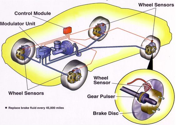
systems, there are three major components for ABS which are as follows:
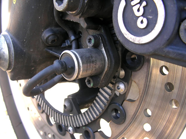
1) Wheel speed sensors
As the toothed wheel rotates the changes in inductance of the
magnetic circuit which generates a signal; the frequency and voltage of which
are proportional to wheel speed.
2) Electronic control unit
The main function of the ECU unit is to take in the information from the wheel
sensors and calculate the best course of action for the hydraulic modulator
unit.
The heart of a modern ECU consists of two microprocessors such as
the Motorola 68HC11, which run the same programme independently of each
other.
It ensures that the greater security against any fault which could
adversely affect the braking performance of the vehicle, because the operation
of each processor should be identical.
If a fault is detected, the ABS system disconnects itself and operates a warning light for attention. Both processors have nonvolatile memory into which fault codes can be written for later service and diagnostic access.
The ECU unit also having a suitable input signal processing stages
and output or driver stages for actuator control.
The ECU unit performs a self-test after the vehicle ignition is
gets switched on. A failure will result in disconnection of the system. The
following list forms the self-test procedure:
1.Current supply;
2.Exterior and interior interfaces;
3.Transmission of data;
4.Communication between the two microprocessors;
5.Operation of valves and relays;
6.Operation of fault memory control;
7.Reading and writing functions of the internal memory.
All this takes about 300 mS!
3) Hydraulic modulator
ABS
hydraulic modulator unit is the part which optimizes brake pressure on each
wheel of the vehicle. It’s mostly always active and monitors when there is a
danger of locking of wheels.
The ABS hydraulic modulator will automatically increase or
decrease the brake pressure to optimize traction.
When a wheel starts to lock, rotational speed is decreased. And
that reduction of speed is detected by the wheel speed sensor. All those
information is interpreted and collected by the electronic brake control module
or EBCM.
Being an electrical device, the EBCM cannot control the hydraulic
brakes, without help of other unit.
The hydraulic modulator allows that an electric current to control
the hydraulic forces. Most of the units include a pump and several solenoid
operated valves. A solenoid is magnetic coil controlled by the ABS
computer.
Symptoms 1:
ABS not working or warning lights on.
Possible causes:
1) Wheel sensor or associated wiring open circuit/high
resistance.
2) Wheel sensor air gap incorrect.
3) Power supply/earth to ECU low or not present.
4) Connections to modulator open circuit.
5) No supply/earth connection to pump motor.
6) Modulator windings open circuit or high resistance.
Symptoms 2:
Warning light comes on intermittently.
Possible causes:
1) Wheel sensor air gap incorrect.
2) Wheel sensor air gap contaminated.
3) Loose wire connection.
Diagnostics of Anti-Lock Braking
System (ABS)
Step wise procedure for Diagnosis of Anti-Lock Braking System:
Step 1: Hands and Eyes tests,
check the fluid levels, and connections security etc.
Step 2: Check out the battery conditions and fuses and supplies of ECU unit.
Step 3: Start scanning for DTCs if test equipment is available.
Step 4: Now check the operations of the brakes at normal conditions.
Step 5: Check the wheel sensor operations, check clean regular sine wave output proportional to wheel speed. This is intermediate step whether output is going to clean if NO go to sub-steps as below:
Sub-step 1: Check the sensor air gaps.
Sub-step 2: Renew the sensors.
Sub-step 3: Reset the fault memory in ECU disconnect ABS fuse for
10 seconds. Replace ECU if no other faults found. And finish the diagnostic
process.
Repeat the intermediate step 5, if signal is YES then do the further steps,
Step 6: Check the wire continuity from sensors to ECU unit, signal should be the same at the ECU.
Step 7: Check continuity of wire to modulator assembly.
Step 8: Check the resistance of modulator solenoid valves to equal values.
Step 9: Check the resistance of pump motor up to range of 0.3 – 0.5 or run the pump motor if possible.
Step 10: Check the operation of stop lamp switch in some cases for ABS separate switch placed.
Now, repeat the Sub-step 3 and then end the diagnosis process.
Anti-Lock Braking System
manufacturers
Here is the list of
Automotive Anti-lock Braking System (ABS) manufacturers
1. Brembo brakes.
2. BOSCH.
3. Honda.
4. ZF TRW.
5. BIWI.
6. Continental.


The blog seems to share interesting tips car detailer come to you Virginia Beach. I like this information because I was looking for affordable cars, trucks, vans detailing services in Chesapeake. Maybe I will share with facebook group friends about this blog.
ReplyDelete