Introduction In the world of internal combustion engines, turbochargers have become a popular method of increasing power and efficiency. This gas compressor, often referred to simply as a turbo, is a form of forced induction that forces air into the engine, resulting in more power for a given displacement. In this blog, we will explore the inner workings of turbochargers and their impact on engine performance. The Components of a Turbocharger At its most basic level, a turbocharger consists of three major components: the turbine, the compressor, and the bearing system that supports the turbine shaft connecting the turbine and compressor wheels. The turbine is located on the hot side of the turbocharger and is bolted onto the engine's exhaust manifold. As the engine runs, the exhaust gases pass through the turbine, spinning a fan called the turbine wheel. This spinning motion converts heat and pressure into rotational force, which in turn spins the compressor whee...
Welcome to Explore Automotive, In this blog we will see the automotive clutch, How automotive clutch works? and How automotive clutch classified? and specially role of clutch in manual transmission vehicles.
In
an automobile, the mechanism which is playing major role to transmits the power
developed by the engine to the wheels or tracks and accessory equipment is called
the power train. In application, a set of gears or a chain and sprocket could
perform this task.
However, automotives and construction equipments are not generally
designed for such a simple operating conditions. They are to be designed which
provides the pulling power, to move the equipment at high speeds, to travel in
a reverse as well as forward direction, and to operate easily on a rough
terrain as well as smooth road conditions. To meet these type of varying
conditions, vehicle power trains are equipped with a different variety of
components. In this blog we discuss the basics of automotive clutches.
Automotive Clutches
An
automotive clutch is used generally in all types of automobiles which connect
and disconnects the engine and manual transmission or transaxle. The clutch is usually
placed in between the back of the engine and the front of the transmission.
With
avoiding a few exceptional cases, the clutches common to the Naval Construction
Force (NCF) equipments are of the single, double, and multiple-disc types. The
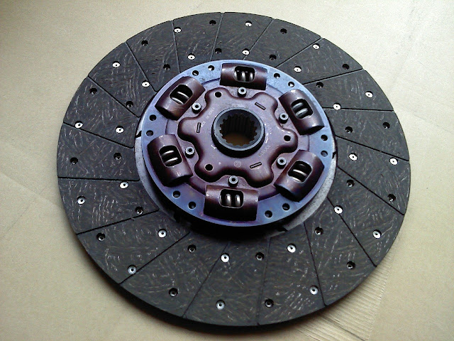
clutch that mostly used in automobiles is the single-disc type (Figure 1).
Figure 1: Single Disc Clutch
The double-disc clutch is nearly the same as of the
single-disc, except that another driven disc and an intermediate driving plate
are to be added. This type of clutch is mostly used in heavy-duty vehicles and
in construction equipments. The multiple-disc clutch is used in the automatic transmissions and for the steering clutch used in tracked equipment and in
motorcycles also.
Operating
principles, different component functions and maintenance requirements are
essentially the same for all types of three clutches mentioned. This being the
case, the single-disc clutch will be used to understand you with the
fundamentals of the clutch.
A) Clutch Construction
The
clutch is the first unit in drive train component which is powered by the
engine crankshaft. The clutch lets the driver control power flow between the
engine and transmission or transaxle. Before understanding the operation of a
clutch, we must know about the parts and their functions. This information is
very useful when we start learning to diagnose and repair the clutch assembly.
1. Clutch
Release Mechanism
A
clutch release mechanism allows that the operator to operate the clutch.
Generally, this mechanism consists of the clutch pedal assembly, a mechanical
linkage, cable, or hydraulic circuit, and the clutch fork. Some of the manufacturers
include the release bearing as part a of the clutch release mechanism.
2.1 Linkage
Clutch linkage mechanism uses different levers and
rods to transfer the motion from the clutch pedal to the clutch fork. One of
the configurations is shown in Figure 2. When the clutch pedal is pressed by the driver, a pushrod
shoves on the bell crank lever and the bell crank reverses the forward movement
of the clutch pedal.
Figure 2: Clutch Linkage
And the other end of the bell crank lever is connected to
the release rod. Then the release rod transfers the bell crank lever movement
to the clutch fork. It also provides adjustment method for the clutch.
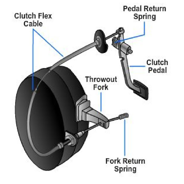
2.2 Cable
Clutch cable mechanism uses a steel cable which is
covered with flexible housing to
transfer the pedal movement to the clutch fork. As shown in Figure 3, the cable is
generally fastened at the upper end of the clutch pedal, with the other end of
the cable connected to the clutch fork.
Figure 3: Clutch Cable
The cable housing is mounted in a
stationary position in such a way that it allows the cable to slide or move
inside the housing whenever the clutch pedal is press or release. At one end of
the clutch cable housing having a threaded sleeve for the clutch adjustment.
3. Hydraulic
Hydraulic clutch release mechanism working on a
simple hydraulic circuit which helps to transfer the clutch pedal action to the
clutch fork (Figure 4). It
has three basic parts that are master cylinder, hydraulic lines, and a slave
cylinder.
Figure 4: Hydraulic Clutch
Movement of the clutch pedal generates hydraulic pressure in the
master cylinder, which is actuating the slave cylinder. Then the slave cylinder
moves the clutch fork.
3.1 Slave
Cylinder with Clutch Master Cylinder
Master
cylinder is the main controlling cylinder which develops the hydraulic pressure.
The slave cylinder is an operating cylinder that actuated by the hydraulic
pressure developed by the master cylinder.
4. Clutch
Fork
The
clutch fork which is also called as clutch arm or release arm which transfers
the motion from the release mechanism to the release bearing and pressure
plate. The clutch fork coupled through a square hole in the bell housing and
mounted on a pivot.
When the clutch fork is tends to move by using the release
mechanism, it pries on the release bearing to disengage the clutch. A rubber
boot fitted over the clutch fork which is designed to keep away road dirt,
rocks, oil, water, and other debris from entering the clutch housing.
5. Clutch
Housing
Clutch
housing is also called the bell housing. It bolted to the rear of the engine
which encloses the clutch assembly, with the manual transmission bolted to the
back of the housing.
The lower front of the housing having a metal cover that
can be able to remove for the flywheel ring gear inspection or when the engine
must be separated from the clutch assembly. A hole is provided at the side of
the housing for the clutch fork. It can be made of aluminum, magnesium, or cast
iron.
6. Release
Bearing
Release
bearing also called as the throw-out bearing which includes a ball bearing and
collar assembly. It controls or minimizes the friction between the pressure
plate levers and the release fork.
The release bearing is completely sealed
unit pack with a lubricant. It slides over a hub sleeve which is extending out
from the front of the manual transmission or transaxle and is moved by using either
hydraulic or manual pressure.
7. Hydraulic
Type
Hydraulic
release bearing avoids the stock mechanical release bearing linkage and the slave
cylinder. The release bearing mounted on the transmission face or slips over
the input shaft of the transmission system.
When the clutch pedal is to be
pressed, the bearing face presses against the pressure plate to disengage the
clutch of the vehicle.
8. Manual
Type
Release
bearing taking over the end of the clutch fork. Small spring clips which holds
the bearing on the fork. Then the fork movement takes place in either direction
slides the release bearing along the transmission hub sleeve.
9. Pressure
Plate
Pressure
plate is a spring-loaded device that can either engage or disengage the clutch plate
disc and the flywheel by applying the pressure when pedal pressed. It is
connected to the flywheel.
The clutch disc fits in between the flywheel and the
pressure plate. Now, there are two types of pressure plates—the one is coil
spring type and another one is that diaphragm type.
9.1 Coil
Spring Pressure Plate
Coil
spring type pressure plate uses a small coil springs which are similar to the
valve springs (Figure 5). The face of the pressure plate is a large,
flat ring which comes in contacts with the clutch disc during clutch
engagement.
Figure 5: Coil Spring Pressure Plate
The back side of the pressure plate having pockets for the coil
springs and brackets which used to hinging the release levers. During
the clutch action, the pressure plate moves backward and force inside
the clutch cover.
The release levers are hinged inside the pressure
plate to pry on and move the pressure plate face outwards from the clutch plate
disc and flywheel. Small clip-type springs are fitted around the release
levers to keep them rattling when gets fully released.
The pressure
plate cover fitted over the springs, the release levers, and the
pressure plate face. Its main purpose is to hold the whole assembly together as
a unit. Holes which are surrounded by the outer edge of the cover are for
bolting the pressure plate to the flywheel.
9.2 Diaphragm
Pressure Plate
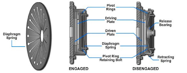
As
shown in (Figure 6), the diaphragm pressure plate uses a single
diaphragm spring instead of the coil springs. The diaphragm spring is a large,
round disc made up of spring steel.
Figure 6: Diaphragm Pressure Plate
The spring is bent or dished and has
pie-shaped segments which is running from the outer edge to the center. The
diaphragm spring is mounted in the pressure plate with the outer edge which touching
the back of the pressure plate face.
The outer rim of the diaphragm is getting
secured to the pressure plate and is pivoted on rings approximately 1 inch from
the outer edge off the same.
By
the application of pressure at the inner section of the diaphragm will cause
the outer rim to move outward from the flywheel and draw the pressure plate
away from the clutch disc, disengaging the clutch.
10. Clutch
Disc
10.1 Wet
Type
A
“wet” clutch is always immersed in a cooling lubricating fluid, which also
keeps the surfaces to be clean and gives smoother performance enhancements and
longer life. Wet clutches tends to lose some energy to the lubricating liquid.
Since, the surfaces of wet clutch can be slippery in condition, stacking with
multiple clutch discs which can compensate for the lower coefficient of
friction and so eliminate the slippage under the power when fully engaged.
Wet
clutches are designed in such a way that which provides a long, service-free
life. They often last the entire life of the machine in which they are
installed on. For maintenance, we must need to refer the manufacturer’s manual.
10.2 Dry
Type
Clutch
disc which is also called as friction lining is a “dry” clutch and it consists
of a splined hub and a round metal plate which is covered with friction
material (lining).
The splines in the center of the clutch disc meshing with
the splines which are on the input shaft of the manual transmission. This
condition makes the input shaft and disc to be turn together.
However, the disc
is free to slide backward and forward on the shaft. Clutch disc torsion springs
which are also termed as damping springs, absorbs some of the
vibration and shock which produced by the clutch engagement.
Damping springs
are small coil springs which located in between the clutch disc splined hub and
the friction disc assembly. When the clutch is getting engaged, the pressure
plate jams the stationary disc against the spinning flywheel.
The torsion
springs get compress and soften as the disc first begins to turn with the flywheel.
Clutch disc facing springs which are also called as the cushioning springs.
These are flat metal springs located under the friction lining of the disc.
These springs have a slight wave or curve, which allowing the lining to flex
inward slightly during the initial engagement and also allows for smooth
engagement.
The clutch disc friction material, also called as disc lining or
facing, which is made up of heat resistant asbestos, cotton fibers, and copper
wires woven or molded together. Grooves are cut into the friction material to
provide aid cooling and release of the clutch disc. Rivets are used to bond the
friction material on to the both sides of the metal body of the disc.
11. Flywheel
The
flywheel is the main mounting surface for the clutch (Figure 7). The
pressure plate bolted to the flywheel face. The clutch disc is clamped and held
against the flywheel by using the spring action of the pressure plate.
Figure 7: Flywheel and Pilot Bearing
Face of
the flywheel is precision machined which is a smooth surface. The face of the
flywheel that touches the clutch disc which is made up of iron. Even if the flywheel
were aluminum, the face is made of iron because it wears well and helps to
dissipates heat better.
12. Pilot
Bearing
The
pilot bearing or bushing is to be pressed into the end of the crankshaft to
support the end of the transmission input shaft (Figure 7). The
pilot bearing is a solid bronze bushing, but it can also be a roller or a ball
bearing.
The end of the transmission input shaft has a small journal which is
machined on its end. This journal slides at the inner side of the pilot
bearing. Pilot bearing prevents the transmission shaft and clutch disc from the
effect of wobbling up and down when the clutch is released. It can also assist
the input shaft at center of the disc on the flywheel.
B. Clutch Operation
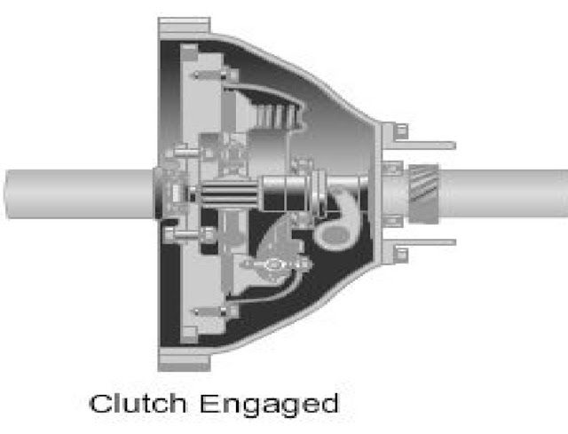
When
the operator or driver of the vehicle presses the clutch pedal, the clutch
release mechanism pulls or pushes on the clutch release lever or clutch fork (Figure 8).
Figure 8: Clutch Operation
The fork moves the release bearing into the center of the
pressure plate, which causing the pressure plate to pull outward direction from
the clutch disc which releasing the disc from the flywheel. The engine
crankshaft can be turn without turning the clutch disc and transmission input
shaft.
When the operator or driver of the vehicle releases the clutch pedal,
spring pressure inside the pressure plate pushes forward on the clutch disc.
This action get locks the flywheel, the clutch disc, the pressure plate, and
the transmission input shaft together.
The engine again starts to rotate the
transmission input shaft, the transmission gears, the drive train, and the
wheels of the vehicle.
C. Clutch Start Switch
Many of the new vehicles coming in the markets incorporate a
clutch start switch into the starting system. The clutch start switch is
mounted on to the clutch pedal assembly.
The clutch start switch helps to
prevent the engine from cranking unless the clutch pedal is depressed fully.
This switch act as a safety device that keeps the engine from possibly starting
while in geared condition.
Unless the switch is to be closed (clutch pedal
depressed), that switch also prevents current from reaching the starter
solenoid. With the transmission in neutral condition, the clutch start switch
is bypassed so the engine will crank and get start.
D. Clutch Adjustments
Clutch adjustments are to be made to compensate the wear of the
clutch disc lining and linkage between the clutch pedal and the clutch release
lever. This adjustment involves setting the correct amount of free play in the
release mechanism.
Too much free play can causes the clutch to drag during
clutch disengagement condition. And too little free play can also cause the
clutch slippage. So, It is important for us to know that how to adjust the
three types of clutch release mechanisms.
Mechanical clutch linkage is to be adjusted at the release rod
which going to the release fork shown in (Figure 2). At one end of the
release rod is to be threaded.
The effective length of the release rod can be
increased to raise height of the clutch pedal (decrease free travel). It
can also be decrease to lower height of the clutch pedal (increase free
travel).
To change the clutch adjustment, simply loosen the release rod
nuts placed on it. Turn the release rod nuts on to the threaded rod until we
reached the desired free pedal travel.
2. Pressure Plate Adjustment
When a new pressure plate is to be installed,
always remember that to check the pressure plate for the proper adjustments.
These adjustments will ensure that proper operation of the pressure plate.
The
first adjustment ensures that proper movement of the pressure plate is to be
done in relation to the cover. As shown in Figure 9, with the use of a straight edge and a scale, begin turning the
adjusting screws until we obtain the proper clearance between the straight-edge
and the plate as shown.
Figure 9: Pressure Plate Adjustment
For exact measurements, please refer the manufacturer’s
service manual of particular vehicle. For the second adjustment which is
important for proper operation in which the release lever allows the release
bearing to contact the levers simultaneously while maintaining the adequate
clearance of the levers and disc or the pressure plate cover. This adjustment
is called as a finger height.
To do the adjustments for the pressure plate,
place the assembly on a flat surface and measure the height of the levers, as
shown in Figure 10.
Figure 10 Pressure Plate Release Lever Adjustment
And adjust it
by loosening the locknut and turning, after the proper height has been set,
make sure that the locknuts are to be locked and staked properly with a punch
to keep it from getting loose during the operations. Exact release lever height
can be taken into consideration from the manufacturer’s service manual.
3. Clutch Cable Adjustment
Like the mechanical linkage, a clutch
cable adjustment is to be required to maintain the correct pedal height and
free travel according to the operator. Typically the clutch cable having an
adjusting nut.
When the nut is to be turned, the length of the cable housing get
increases or decreases as per movement. To increase the clutch pedal free
travel, turn the clutch cable housing nut to shorten the cable housing, and, to
decrease clutch pedal free travel, turn the nut to lengthen the cable housing.
E. Hydraulic Clutch
Hydraulically operated clutch is to be
adjusted by changing the length of the slave cylinder pushrod. To adjust the
hydraulic clutch, simply turn the nut or nuts which are placed on the pushrod
as per requirement.


Comments
Post a Comment
If you have any doubts and queries please let me know